About Press Copyright Contact us Creators Advertise Developers Terms Privacy Policy & Safety How YouTube works Test new features Press Copyright Contact us Creators. A bell-crank lever consists of a long arm, 8 1 2 in. Long, and a short arm 4 in. Long, at right angles to each other. Calculate the force to be applied at right angles to the end of the long arm to overcome a resistance of 40 lbf acting at 30° to the vertical of the short arm. Video Lecture on Problem on Bell Crank Lever from Design of Cotter Joint, Knuckle Joint,Levers and Offset Links Chapter of Design of Machine for Mechanical. Abstract - Bell Crank Lever is important components from safety point of view since they are subjected to large amount of stresses. Hence to study the stress pattern in bell crank lever, analytical, numerical and photoelasticity methods are used. For analysis purpose virtual model of bell crank lever is prepared.
What is a lever?
A lever is a rigid bar that pivots about a fulcrum. It transmits an input motion and force, (the effort) through the lever pivoting on a fulcrum to a resistance force called a load.
Load
The load is anything that is being moved by a lever.
Effort force
The effort force is the energy applied to a lever to move a load.
Fulcrum
The fulcrum is the point at which the lever pivots. A lever may rest on a fulcrum or it may swivel on an axle, e.g. a see-saw (class 1 lever) and a wheel barrow (class 2 lever).
Classes of lever
There are three classes of levers. Each class of lever has the load and effort force in specific positions relative to the fulcrum.

Suspension Bell Crank
Class 1 lever

A Class 1 lever has the fulcrum between the load and the effort force.
Class 2 lever
Bell Crank Design
A Class 2 lever has the load between the fulcrum and the effort force.
Class 3 lever


A Class 3 has the effort force between the load and the fulcrum.
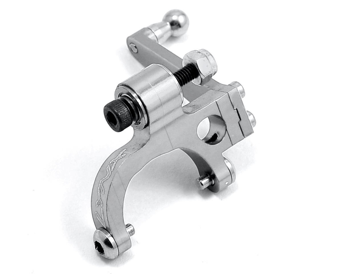
Bell Crank LeverA bell crank lever is an angled Class 1 lever. It is a Class 1 lever because the fulcrum is between the load and the effort force. The bell crank lever is used when the effort force must be at an angle, usually a right angle, to the load. |
CantileverA cantilever is a beam that is fixed at one end only. Load is applied to the unsupported end. A cantilever may be classified as a type of Class 1 lever as fulcrum is between the effort force and the load. |
Bell Crank Mechanism
- Fornace, L.V.: Weight Reduction Techniques Applied to Formula SAE Vehicle Design: An Investigation in Topology Optimization (2006)Google Scholar
- Muhammad Sahail, B. Zainol Abidin.: Design and Development of a Bell Crank for Monoshock Front Suspension for Formula Varsity Race Car. Melaka, universiti teknikal malaysia melakaGoogle Scholar
- Borg, L.T., West, R.L., Ferris, J.B., Member, C., Merkle, M.A.: C.Member Borg_L_ETD_Copy_07-26-2009.pdf (2009)Google Scholar
- Dange, M.M.M., Zaveri, S. R., Khamankar, S.D.: International Journal on Recent and Innovation Trends in Computing and Communication Stress Analysis of Bell Crank Lever (2014)Google Scholar
- Zende, S.R., Shaikh, M.R., Dolas, D.R.: International Journal of Modern Trends in Engineering and Research Fillet Radius Optimization of Bell Crank Lever (1947)Google Scholar
- Patel, R.C., Sikh, S.S., Rajput, H.G.: Machine Design (1992–93)Google Scholar
- Chan, W.H., Chan, A.H.S.: Strength and reversibility of movement stereotypes for lever control and circular display. Int. J. Ind. Ergon. 37, 233–244 (2007)Google Scholar
- Allegrucci, L., Amura, M., Bagnoli, F., Bemabei, M.: Fatigue fracture of a aircraft canopy lever reverse. Eng. Fail. Anal. 16, 391–401 (2009)Google Scholar
- Liu, Y.: Recent innovations in vehicle suspension systems. Recent Pat. Mech. Eng. 1, 206–210 (2008)Google Scholar
- Gyllenskog, J.D.: Fatigue life analysis of T-38 aileron lever using a continuum damage approach. All Graduate Theses and Dissertations (2010)Google Scholar
- Jouaneh, M., Yang, R.: Modeling of flexure-hinge type lever mechanisms. Precis. Eng. 27(4), 407–418 (2003)Google Scholar
- Bos van den P.: Design of a Formula Student Race Car Spring-Damper System. Eindhoven, Technische Universiteit (2010)Google Scholar
- Emey, T., Chrysler, D.: Combination of topology and topography optimization for sheet metal structures. Altair Eng. Ger. AIAA 2000-4946Google Scholar